Supercharged V8 power. Engineered as a complete system.
Gen V LT4 dry-sump crate engine
Factory power
650 hp
Factory torque
650 lb-ft
Displacement
6.2 liters
Supercharger
1.7 liters
Engine weight Dry-sump LT4
~330 lb
Transmission weight Graziano six-speed manual
120–140 lb
Factory LT4 ratings; this build's measured output is not documented here.
Chevrolet specifications
LT4
Loading engine model…
Drag to rotate. Arrow keys turn, Home resets, Space pauses. Rotation resumes 3
seconds after release.
Assembled study.
CONTROLLED TURNTABLE · 360° Original illustrative geometry. Reference
accessories may differ from the build.
BEYOND THE ENGINE
Oil. Cooling. Control.
Dry-sump lubrication
An AVIAID dry-sump tank complements the LT4's dry-sump configuration.
Thermal management
Dual Mishimoto intercoolers are part of the build's cooling system.
Engine management
The stock GM ECU, with HP Tuners for calibration and diagnostics.
02 / DRIVETRAIN
Every shift. A connection.
A six-speed Graziano manual transaxle as seen in the Audi R8 and Lamborghini
Gallardo.
Modified with an HCF drop gear to match the LT4’s characteristics.
6 MT
Press Space or Enter on the model to pause or resume animation.
CONSTANT-MESH MOTION STUDY Illustrative geartrain, not the exact
Graziano internals. One ratio engaged; the remaining output gears freewheel.
TRANSAXLEGraziano 6-speed
FLYWHEELHCF
CLUTCHTilton twin-disc
THE CONNECTION
Gearing with a purpose.
The HCF drop gear adapts the Graziano to the lower-revving LT4. An HCF flywheel and
Tilton twin-disc clutch complete the connection between engine and transaxle.
THE NEXT CHAPTER
A whole car. A thousand decisions.
Suspension. Electronics. A planned active wing. Return to the car to explore each
system as the build takes shape.
The workshop photograph shows Colin's actual car. The rotating engine and gearstack
are original illustrations, not dimensioned CAD or a record of completed
installations.
The
LT4 photo reference
shows a modified engine. Its output figures, internal modifications, and oil-pan
configuration are not claims about this build. The
Graziano reference
depicts the OGeco hybrid concept, a different transmission. No reference photography
is embedded in these illustrations.
02 / ELECTRONICS
Power. Data. Driver.
A clear driver interface, managed electrical loads, and factory engine control. The
next layer is a custom controller for active aero.
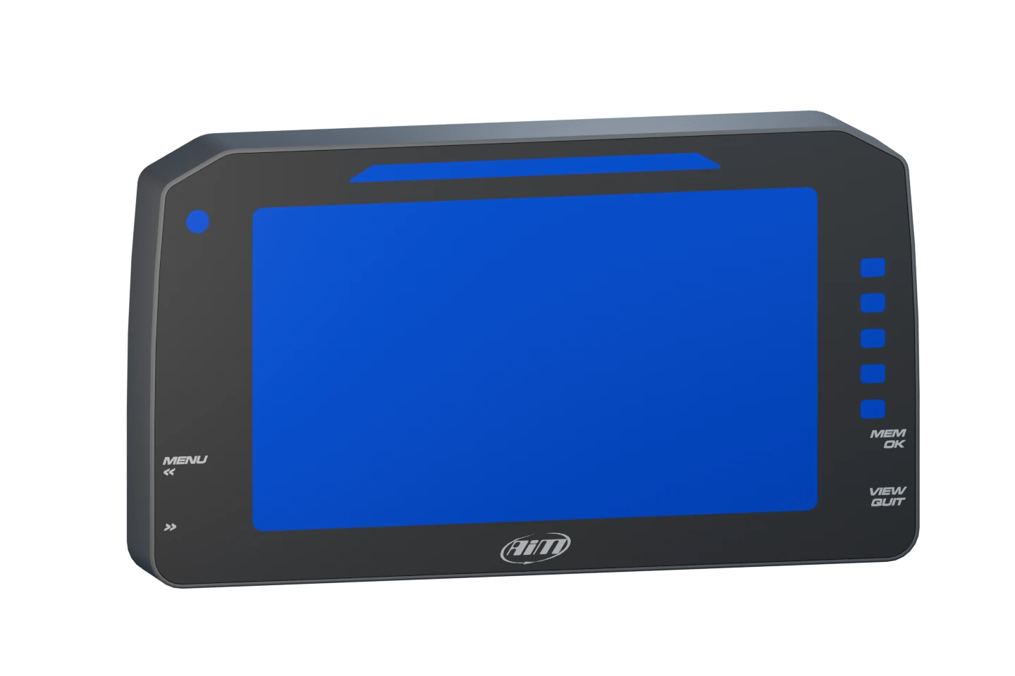
SUPPLIED D6 HARDWARE REFERENCE
The information
that matters.
An AiM 6-inch PDM display puts vehicle data and warnings in the driver's
sightline. The supplied D6 CAD gives the dashboard packaging a real hardware
envelope.
Rendered from the supplied D6 geometry. The blue screen is the CAD material, not
live telemetry.
PDM / EXACT MODEL TO CONFIRM
Distribute.
Protect. Diagnose.
Power distribution brings electrical loads, circuit protection, and fault
feedback into a managed system. Output assignments and protection settings
follow the actual module and loom design.
Role
Power switching & protection
Build record
Hardware model and circuit setup to document
POWER DISTRIBUTIONILLUSTRATIVE
Original enclosure and functional study. Connector shapes and output count do
not specify the build hardware.
CONFIRMED BUILD EQUIPMENT
Factory control.
Build-specific calibration.
The stock GM ECU anchors LT4 engine management. HP Tuners provides the
calibration, scanning, and data-logging workflow for understanding and refining
its operation.
Original controller illustration. The exact GM ECU part number and enclosure are
unconfirmed.
PLANNED / CUSTOM CONTROLLER
A separate
control problem.
The active wing needs its own sensing, actuation, and fail-state decisions.
Custom aero control is planned; the operating strategy and physical integration
remain engineering work to complete.
Scope
Active-aero control & DRS
Next decisions
Actuation, limits & failure behaviour
ACTIVE AERO / CONTROL STUDYPLANNED
Functional concept, not an installed wiring diagram or validated control law.
BUILD IN PROGRESS GM ECU and HP Tuners are confirmed. AiM display
geometry is supplied; installation and final display setup are still to document. PDM
identification is pending. Custom active-aero control is planned.
03 / SUSPENSION
DESIGN IN PROGRESS
Geometry first. Adjustment second.
The rear cantilever needs a rethink. Then comes the tuning: QA1 MOD dampers,
Hyperco springs, and front and rear sway bars designed around this chassis.
Drag to rotate. Arrow keys turn, Home resets, Space pauses. Rotation resumes 3
seconds after release.
EXTERNAL QUICKTUNE DETAIL
Illustrative service-access separation. Packs are offset for visibility; internal
valving is not reconstructed.
Illustrative technical component study.
Attached canister and valve-pack details are a reference-based visual study.
01 / REAR CANTILEVER
Get the leverage right.
The rocker translates wheel movement into damper movement. Reworking its pivots
and pickup points lets us shape motion ratio and progression, use the available
damper stroke, and keep clearance through bump and droop.
Motion ratio = shock movement ÷ wheel movement.
Hardpoints, ratios and travel margins still need to be established on the car.
KINEMATIC STUDYSCHEMATIC / NOT TO SCALE
1 Wheel + pushrod2 Rocker pivot3 Damper stroke
DROOPBUMP
Illustrative linkage only. The control demonstrates the relationship, without a
measured ratio or travel claim.
02 / QA1 MOD SERIES
Room to tune.
Independent high- and low-speed compression and rebound adjustments give the MOD
series four ways to shape damping. “Speed” means shock shaft speed, not road
speed.
The piggyback nitrogen canister attaches directly to the shock base. QuickTune’s
external compression and rebound valve packs can be swapped on the car. This study
adds those visible features to the supplied coilover CAD; final dimensions and
full-travel clearance remain design tasks.
COMPRESSIONREBOUND
LOW SHAFT SPEED
↘ Body control
↗ Extension control
HIGH SHAFT SPEED
↘ Sharp inputs
↗ Fast extension
Adjustment functions overlap. Final valving and settings need testing.
03 / FRONT + REAR SWAY BARS
Build the balance.
Designing both bars from scratch gives us control of packaging, lever arms and
front-to-rear roll stiffness. The aim: tune roll resistance and handling balance
without relying only on stiffer road springs.
Bar section, arm length, links and mounts will be developed together. Loads,
clearance, fatigue and vehicle testing still need to validate the design.
ANTI-ROLL PRINCIPLEONE AXLE / SCHEMATIC
1 Chassis mounts2 Torsion section3 Arms + end links
Opposite wheel movement twists the bar, adding roll resistance. Front and rear bar
choices set the balance together.
04 / ACTIVE AERO · PLANNED
One wing. Two intentions.
Rear element raised.
The rear element sits at its higher illustrative angle. Select DRS to flatten its
orientation.
Drag to rotate. Arrow keys turn, Home resets, Space pauses. Rotation resumes 3
seconds after release.
WING ONLY / ILLUSTRATIVE ESTIMATE
Speed. Squared.
Illustrative, unvalidated wing-only model. GT3 RS coefficients have not been
verified; both coefficients below are arbitrary assumptions.
F↓ = ½ ρ v² S C↓
Use density 0.1–2 kg/m³, reference area 0.01–5 m², and coefficients 0–4. Empty or
invalid inputs cannot produce an estimate.
Downforce position
Assumed C↓ =
lbf ↓
N
F↓ = 0.5 × ρ × v² × S × C↓
DRS position
Assumed C↓ =
lbf ↓
N
F↓ = 0.5 × ρ × v² × S × C↓
JavaScript enables the speed control, editable assumptions and estimates. The force
equation remains available as an educational model.
Assumptions, area & sources
ASSUMED OVERALL SPAN70 in / 1.778 m
SHARED REFERENCE AREA S
Example area only until the local CAD footprint is available.
The 210 mph slider limit is a chosen illustration range, not a measured top speed.
A separate, provisional gearing estimate is about 205.7 mph at 6,600 rpm with
325/25ZR20 rear tires, 0.70 sixth gear, an assumed 1.04 drop gear and 3.462 final
drive. Tire rolling diameter and gearing assumptions are not verified as an
operating speed.
Positive force means downforce. The same reference area is used for both
positions; their assumed coefficients create the difference. Car speed assumes
still air.
The 1.00 / 0.30 coefficients are arbitrary examples, not verified GT3 RS values or
CFD / wind-tunnel results. This estimates wing-only vertical force, not whole-car
aero, drag reduction or setup guidance. Real coefficients vary with angle and flow
conditions.
Porsche's published total-car downforce
does not establish coefficients for this wing or these poses.
Conversions: v (m/s) = speed (mph) × 0.44704; 1 lbf = 4.448221615 N. Model:
NASA lift equation, using a positive-downward coefficient convention.
The wing and custom control modules are planned. Integration, actuation, control
logic, and validation remain future work.